[su_image_carousel source=”media: 52349,52350,52351,52352″]
Introduction
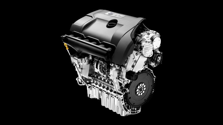
Production of Volvo’s ‘Short Inline 6’ (SI6) engine (code: B6324S) commenced in March 2006. Although manufactured at Ford’s engine plant in Bridgend, Wales, the SI6 engine was designed, engineered and developed entirely by Volvo.
The SI6 engine had 84.0 mm bores – spaced at 91.0 mm intervals – and a 96.0 mm stroke for a capacity of 3192 cc. Key features of the SI6 engine included its:
- Cylinder block and bedplate which were produced from high-pressure die-cast AlSi9Cu3 aluminium alloy;
- Cast-in iron cylinder liners which were thermally sprayed for a porous AlSi12 coating;
- Gravity-cast AlSi9Cu3 cylinder head which featured cross-flow cooling;
- Double overhead camshafts (chain-driven by gears at the rear end of the crankshaft);
- High-pressure die-cast aluminium camshaft cover which incorporated integrated upper cam bearing halves and oil distribution grooves for Variable Cam Timing (VCT) and Cam Profile Switching (CPS) control;
Four valves per cylinder; - Variable Intake System (VIS);
- Conventional port fuel injection (PFI);
- Compression ratio of 10.8:1;
- Denso engine management system for the fuel and ignition systems; and,
- Mass of 180 kg.
Upon its release, the SI6 engine complied with Euro 4 and ULEV II emissions standards.
Compact design
Since the SI6 engine was mounted transversely, compact dimensions were an important design objective and this was achieved by using Rear End Ancillary Drive (READ). With READ, ancillaries such as the power steering pump and air conditioning compressor were positioned behind the engine (i.e. above the gearbox) and belt-driven via gears at the rear end of the crankshaft. Furthermore,
- The alternator was directly driven and installed on the engine block; and,
- A fluid-type internal viscous damper (IVD) – which compensated for vibration in the six-cylinder engine’s relatively long crankshaft – was integrated into the engine block.
Compact dimensions also improved occupant protection since there was additional space for deformation in the engine compartment and reduced the risk of head injuries for pedestrians and cyclists by creating additional space for the bonnet to crumple.
The SI6 engine was 705 mm high, 625 mm long and 728 mm wide.
Cam Profile Switching (CPS)
Cam Profile Switching (CPS) allowed the engine’s intake valves to be lifted to two heights based on demand using an intake camshaft equipped with three lobes per valve. The central lobe at each valve provided a low lift height of 3.6 mm, and two outer, equal-sized lobes provided the higher lift height of 10 mm. At low engine speeds and moderate throttle inputs, low valve lift improved fuel efficiency. At high engine speeds and full throttle, however, the CPS-tappet (a two-piece, hydraulic valve tappet) would switch to engage the second set of cam lobes to produce high valve lift and increase the volume of the air-fuel mixture to each cylinder for greater power. The switch between low and high lift would occur between 1200 and 3300 rpm, depending on engine load.
Variable Cam Timing (VCT)
The SI6 engine had Variable Cam Timing (VCT) which could adjust when the inlet valves opened and closed (in combination with CPS). Strategies for VCT and CPS included:
- Start-up: the inlet valve would close at bottom dead centre (BDC), use low valve lift and open late for quick engine rev-up;
- Low and medium engine speeds and partial load: the inlet valve would close very early, use low lift and open early to reduce pumping losses;
- Medium engine speeds and high load: the inlet valve would close early, use high valve lift and open late to enhance volumetric efficiency; and,
- High engine speeds and high loads: mid-range inlet valve opening and high valve lift for volumetric efficiency.
Variable Intake System (VIS)
The SI6 engine had a Variable Intake System (VIS) which used two throttle flap valves to adjust intake tract length and plenum volume. At low engine speeds, the throttle flaps would be closed to lengthen the intake tract – this increased the pulsing effect of the airflow and drew more air into the cylinder. At higher engine speeds, however, the throttle flaps would open to shorten the length of the intake tract, reduce intake resistance and allow a greater volume of air into the cylinder. The VIS reduced pumping losses due to throttling and, according to Volvo, achieved a 4 per cent reduction in fuel consumption.
B6324S5 engine: May 2010 update
In May 2010, Volvo announced that it had replaced its B6324S engine with the B6324S5 engine which had an improved crankshaft, measures which reduced internal friction and produced peak power of 180 kW; a Partial Zero Emissions Vehicle (PZEV) was also introduced for the US market. From a subsequent announcement on the related B6304T4 engine, AustralianCar.Reviews understands that a Diamond-like Carbon (DLC) coating – which had self-lubricating properties – was also introduced for the valve tappets to reduce camshaft friction. Other changes included:
- Denso ‘Super Ignition’ spark plugs for better cold starting performance and longer service life;
- Revised frame bearings within the crankshaft;
- A low-friction accessory drive belt tensioner;
- Engine management software that was optimised for fuel economy;
- Revised mapping software for the ‘Geartronic’ transmission that allowed a new ‘Sport’ mode; and,
- An aluminium water pump housing.
These updated engines had the engine code B6324S5.
[su_table responsive=”yes”]
| Code | Engine | Power | Torque | Models | |
|---|---|---|---|---|---|
| 3.2 | B6324S | 3192 cc petrol I6 | 175 kW at 6200 rpm | 320 Nm at 3200 rpm | 2007 Volvo XC90 3.2, 2007 Volvo S80 3.2, 2008 Volvo V70 3.2, 2008 Volvo XC70 3.2, 2010 Volvo XC60 3.2 |
| 3.2 | B6324S5 | 3192 cc petrol I6 | 180 kW at 6200 rpm | 320 Nm at 3200 rpm | 2011 Volvo S80 3.2, 2011 Volvo V70 3.2, 2011 Volvo XC70 3.2, 2011 Volvo XC60 3.2 |
| 3.2 PZEV | B6324S2, B6324S4 |
3192 cc petrol I6 | 172 kW | 300 Nm | USA only |
[/su_table]
Volvo 3.2 SI6 oil consumption
In April 2012, Volvo issued Technical Journal 24643 for Volvo S80, V70, XC60, XC70 and XC90 vehicles that had 3.2 SI6 engines (codes: B6324S, B6324S2, B6324S4 and B6324S5) that were manufactured prior to 4 May 2011. According to the Technical Journal, these vehicles may exhibit the following symptoms:
- Low oil level;
- Excessive oil consumption;
- Poor idle quality;
- White smoke from the exhaust;
- An oil smell; and/or
- Illumination of the yellow warning symbol and ‘Low oil level’ or ‘Oil level low’ messages in the Driver information Module (SIM).
To determine if the vehicle had an oil consumption condition,
- The engine should be inspected for external leakage on and around the engine, especially around the cylinder head/cam cover/timing cover area. If an external leakage was present, then the following steps were not applicable;
- An oil consumption test could be performed if there was no prior record of low oil levels and oil being added between service intervals;
- The spark plugs were to be examined for evidence of previous oil over-filling since this could be the cause of DTCs related to oil consumption (specifically DTC P030000 and/or P030600). As the Technical Journal acknowledged, these engines were susceptible to over-filling since it was difficult to easily check the oil level with the dipstick;
- A cylinder leakage test was to be performed to determine if oil consumption was coming from an area other than the cam cover;
- If the cylinder leakage tests were OK and if the spark plug from cylinder #6 had more soot than the others, this suggested that the cam cover was not properly sealed from the factory. If so, the cam cover was to be removed so that the sealing surface could be inspected. If the sealing surface was discoloured by oil, it was most likely that there was a leak between the cam cover and the cylinder head in the area facing the positive crankcase ventilation (PCV) channel which connected the breather box and the PCV gallery. To fix, the cam cover was to be re-sealed. The cam cover seal was improved at engine production date 15 April 2010 (15041000001); and,
- If the cylinder leakage tests were OK and there was a spark plug from a cylinder other than #6 which had more soot than the others, then the valve guides were to be inspected. Valve guide leakage was most commonly found when there was excessive white smoke from the exhaust and had been observed on engines with build dates before 4 May 2011 (040511B01272). Each valve guide was to be tested by removing the cam cover, removing the valve tappets, plugging all but one intake port and plugging all intake ports, injector ports and the PCV inlet. Air pressure could then be applied to one intake port at a time and, by using automatic transmission fluid (ATF) for colour differentiation, ripples or bubbles in the ATF would indicate a leak that required the cylinder head to be replaced.
Please note that the testing procedure described above differs for models that have B6324S4 PZEV (‘Engine 94’) or B6324S2 PZEV (‘Engine 96’) engines – these may require new pistons and oil control rings. For information on those engines, please refer to Technical Journal 24643.


