[su_image_carousel source=”media: 52106,52107,52108″]
Introduction
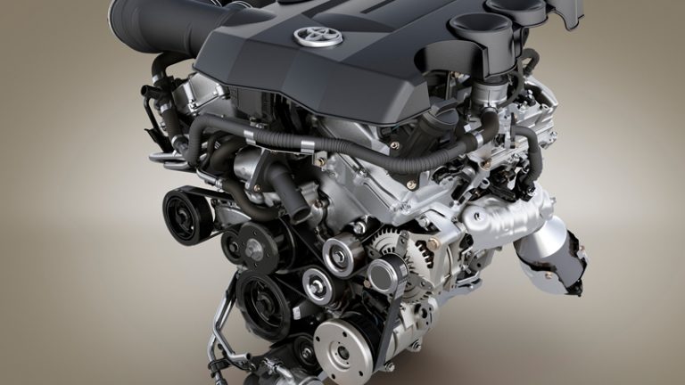
Toyota’s 1GR-FE was a 4.0-litre V6 petrol engine that was first available in Australia in the 2003 Toyota 120-Series LandCruiser Prado, but subsequently offered in the Toyota Mk.7 Hilux. For these vehicles, key features for the 1GR-FE engine included its aluminium alloy cylinder block and head, variable intake valve timing (VVT-i), Acoustic Control Induction System (ACIS) and compression ratio of 10.0:1.
For the 150-Series LandCruiser Prado and FJ Cruiser, however, an upgraded 1GR-FE engine was used which had modified internals, variable intake and exhaust valve timing (‘dual VVT-i), omitted ACIS and had a compression ratio of 10.4:1.
This article will describe attributes of the original 1GR-FE engine and include details of the differences with the upgraded, ‘dual VVT-i 1GR-FE’ engine in turn.
[su_table responsive=”yes”]
| Engine | Trans. | Years | Peak power | Peak torque | |
|---|---|---|---|---|---|
| ToyotaMk.7 Hilux | 4.0-litre petrol V6 | 5sp auto | 2005-15 | 175kW at 5200rpm | 376Nm at 3800rpm |
| 5sp man. | 2005-15 | 175kW at 5200rpm | 343Nm at 2400-4800rpm | ||
| ToyotaMk.8 Hilux | 4.0-litre petrol V6 | 6sp auto | 2015-on | 175kW at 5200rpm | 376Nm at 3800rpm |
| Toyota120 LandCruiser Prado | 4.0-litre petrol V6 | 5sp man., 4sp auto |
2003-04 | 179kW at 5200rpm | 376Nm at 3800rpm |
| 6sp man., 5sp auto |
2004-09 | 179kW at 5200rpm | 376Nm at 3800rpm | ||
| Toyota150 LandCruiser Prado | 4.0-litre petrol V6 | 6sp man., 5sp auto |
2009-15 | 202kW at 5600rpm | 381Nm at 4400rpm |
| 2015-on | 207kW at 5600rpm | 381Nm at 4400rpm | |||
| ToyotaFJ Cruiser | 4.0-litre petrol V6 | 5sp auto | 2011-on | 200kW at 5600rpm | 380Nm at 4400rpm |
[/su_table]
1GR-FE Block
With its die-cast aluminium alloy cylinder block, the cylinder banks of the 1GR-FE engine had a 60-degree ‘V’ angle. The 1GR-FE engine had 94.0 mm bores and a 95.0 mm stroke for a capacity of 3956 cc; bore pitch was 105.5 (i.e. the distance between the centre of adjacent bores), while cylinder bank offset was 36.6 mm. Between the cylinder bores, passages existed for coolant flow.
The 1GR-FE engine had ‘spiny type’ cast-iron cylinder liners. The casting exteriors of these liners had irregular surfaces to enhance the adhesion between the liners and the aluminium cylinder block – this improved heat dissipation and reduced heat deformation of the cylinder bores.
For the dual VVT-i 1GR-FE engine, the surface cross-hatching of the cylinder liner was optimised to improve oil retention performance, thereby reducing friction. Furthermore, cylinder block water jacket spacers were added to the water jacket. The cylinder block water jacket spacers prevented water flow in the middle and below the water jacket, and drew coolant above the cylinder bore for uniform temperature distribution. As a result, the viscosity of the engine oil that acted as a lubricant between the bore walls and the pistons could be lowered, thus reducing friction.
Crankshaft, connecting rods and pistons
For the VVT-i 1GR-FE engine, the forged steel crankshaft had four journals and nine balance weights. The six-bolt main crankshaft bearings were made of aluminium alloy and, like the connecting rod bearings, the lining surfaces were micro-grooved for an optimal amount of oil clearance – this improved cold-engine cranking performance and reduced engine vibration. Furthermore, all pin and journal fillets were roll-finished. The crankshaft bearing caps were tightened using four (4) plastic region tightening bolts for each journal.
For the dual VVT-i 1GR-FE engine, a five balance weight crankshaft was introduced (as per the 2GR-FE); the locations of the balance weights were optimised to reduce vibration and noise.
The 1GR-FE engine had forged connecting rods which used aluminium bearings; for an optimal amount of oil clearance, the lining surface of the connecting rod bearing was micro-grooved. The connecting rods and caps were made of high-strength steel and nutless-type plastic region tightening bolts were used to reduce mass. Furthermore, knock pins were used at the mating surfaces of the bearing caps to minimise movement during assembly.
The 1GR-FE engine had aluminium alloy pistons which had a ‘taper squish’ shape for the piston head. Furthermore, the groove of the top piston ring was coated with anodic oxide to improve wear resistance and rust resistance, while the piston skirt was coated with resin to reduce friction. Oil-cooling jets under the pistons acted to reduce piston temperatures.
For the higher compression ratio of the dual VVT-i 1GR-FE engine (10.4:1 versus 10.0:1), the shape of the pistons was optimised. To reduce weight, cast holes were added on the bottom of the piston head near the pin bosses. The outer surfaces of the second compression ring were also plated with chrome to be compatible with petrol/ethanol blends.
Cylinder head
The 1GR-FE engine had an aluminium alloy cylinder head with steel laminate-type head gaskets. To increase the sealing surface for better durability, a shim was added around the cylinder bore. For the dual VVT-i 1GR-FE engine, the structure of the cylinder head was simplified by separating the camshaft housing (cam journal portion) from the cylinder head.
The cylinder head bolts were positioned below the camshaft journal in the front of the right bank, and the holes for placing the bolts were above the camshaft journal. Furthermore, the 1GR-FE engine had an aluminium cylinder head cover.
CCamshafts
The 1GR-FE engine had double overhead camshafts that were made of cast iron alloy. Both the primary and secondary timing chains used pitch roller chains with a pitch of 9.525 mm. The intake camshafts were driven by the crankshaft via the primary timing chain. The exhaust camshafts were driven by the intake camshaft of the respective bank via the secondary timing chain.
The primary timing chain used one chain tensioner (ratchet type with a non-return mechanism), and each of the secondary timing chains for the right and left banks used one chain tensioner. Both the primary and secondary chain tensioners used a spring and oil pressure to maintain proper chain tension at all times. Furthermore, the timing chains were lubricated by oil jets.
For the dual VVT-i 1GR-FE, the cam lobes had indented R profiles to increase valve lift when the valve began to open and as it finished closing.
Shimless type valve lifters/rocker arms
For valve actuation, the VVTi 1GR-FE had shimless type valve lifters. The dual VVTi 1GR-FE engine, however, had roller rocker arms with built-in needle bearings that reduced the friction that occurred between the camshafts and the roller rocker arms. The hydraulic lash adjuster – located at the fulcrum of the roller rocker arm – consisted primarily of a plunger, plunger spring, check ball and check ball spring. Through the use of oil pressure and spring force, the lash adjuster maintained a constant zero valve clearance.
VVT-i
For the 120-Series LandCruiser Prado andMk.7 Hilux, the variable inlet valve timing (VVT-i) a 50 degree range of adjustment (relative to crankshaft. Furthermore, the 1GR-FE engine had valve overlap of -6 degrees, intake duration of 232 degrees and exhaust duration of 236 degrees.
[su_table responsive=”yes”]
| 1GR-FE VVT-i: Valve Timing | ||
|---|---|---|
| Intake | Open | -8° to 42° BTDC |
| Close | 60° to 10° ABDC | |
| Exhaust | Open | 54° BBDC |
| Close | 2° ATDC | |
[/su_table]Oil passages on the intake and exhaust camshafts enabled the ECU to adjust camshaft advance and retard via:
- An oil control valve (mounted on the cylinder head); and,
- Vane-type actuators on the ends of the intake camshafts.
The ECU also used signals from the camshaft position sensor and the crankshaft position sensor to detect actual valve timing, thus providing feedback control to achieve the target valve timing.
When the engine stopped, the intake side VVT-i controller was locked on the most retarded angle side by the lock pin, and the exhaust side VVT-i controller was locked on the most advanced angle side.
Dual VVT-i 1GR-FE
For the150-Series LandCruiser Prado andFJ Cruiser, the dual VVT-i system could vary inlet valve timing over a range of 40 degrees and exhaust camshaft timing over a range of 35 degrees (relative to crankshaft angle). Maximum valve overlap (the period when both exhaust and inlet valves were open) was 68 degrees for maximum power, while minimum overlap was -7 degrees for optimum economy.
[su_table responsive=”yes”]
| 1GR-FE Dual VVT-i: Valve Timing | ||
|---|---|---|
| Intake | Open | -11° to 29° BTDC |
| Close | 71° to 31° ABDC | |
| Exhaust | Open | 60° to 25° BBDC |
| Close | 4° to 39° ATDC | |
[/su_table]For the dual VVT-i system, there were vane-type actuators on the ends of the four camshafts. The intake side used a VVT-i controller with three vanes, and the exhaust side used one with four vanes.
Intake and ACIS
For the 1120-Series LandCruiser Prado andMk.7 Hilux VVT-i 1GR-FE engine, the intake air chamber was made of plastic and contained an intake air control valve for Toyota’s ‘Acoustic Control Induction System’ (ACIS). ACIS consisted of:
- A bulkhead to divide the intake manifold into two stages; and,
- An intake air control valve in the bulkhead which opened and closed to vary the effective length of the intake manifold according to engine speed and throttle valve opening angle.
When the engine was running at middle speed under high load, an actuator would close the intake air control valve to increase the effective length of the intake manifold and improve intake efficiency – at medium engine speeds – due to the effect of inlet pulsations. In any condition other than middle speed running under high loads, the intake air control valve was open to shorten the effective length of the intake manifold. The dual VVT-i engine, however, omitted ACIS.
The 1GR-FE had straight and upright Siamese-type intake ports to reduce the overall surface area to the intake port walls and prevent fuel from adhering onto the intake port walls (wall wetting).
The 1GR-FE engine had a linkless-type throttle body in which the throttle position sensor and the throttle control motor were integrated. Furthermore, Toyota’s ‘Electronic Throttle Control System – intelligent’ (ETCS-i) controlled the throttle valve in accordance with the amount of accelerator pedal effort and the condition of the engine.
Injection
The 1GR-FE engine had a hot-wire air flow meter to measure intake air mass and a sequential fuel injection system which included a twelve-hole injector for each cylinder. The 1GR-FE engine also had a planar-type air-fuel ratio sensor and oxygen sensor which, according to Toyota, warmed up three times faster than the conventional type to achieve increased mixture accuracy.
For the VVT-i 1GR-FE engine, fuel pressure was 284 kPa; for the dual VVT-i 1GR-FE engine, however, this was increased to 324 kPa for compatibility with ethanol blend fuels. For the dual VVT-i engine, fuel injector was repositioned so that it extended into the intake port; the distance between the injector nozzle end and intake valves was also shortened to reduce wall wetting.
The 1GR-FE used an ‘independent’ injection system in which fuel was injected once into each cylinder for each two revolutions of the crankshaft. Furthermore, there were two injections:
- A synchronous injection in which corrections based on the signals from the sensors were added to the basic injection timing so that injection always occurred at the same position; and,
- A non-synchronous injection in which injection was influenced by signals from sensors (regardless of the crankshaft angle). To protect the engine and improve fuel economy, the system could temporarily cut off fuel supply.
Ignition
The 1GR-FE engine had a coil-on-plug ignition system, Toyota’s ‘Direct Ignition System’ (DIS), in which the spark plug cap was integrated with the ignition coil. Ignition timing was determined by the ECU based on signals from various sensors; the ECU corrected ignition timing in response to engine knocking.
The 1GR-FE had long-reach spark plugs that were positioned in the centre of the combustion chamber. For the VVT-i 1GR-FE engine, the spark plugs were either Denso K20HR-U11 (nickel type) or NGK LFR6C-11 (nickel type). For the dual VVT-i 1GR-FE, the nickel type spark plugs were replaced by Denso SK20HR11 iridium-tipped spark plugs which had 200,000 km maintenance intervals. By adopting an iridium centre electrode, ignition performance was superior to that of platinum-tipped spark plugs and durability was increased.
The 1GR-FE engine had pentroof-type combustion chambers with a ‘taper squish’ shape to improve anti-knocking performance. The squish angle was shaped obliquely along the wall surface of the combustion chamber to improve airflow, promote swirl and accelerate flame travel.
For the VVT-i 1GR-FE engine, the compression ratio of 10.0:1; for the dual VVT-i 1GR-FE, it was 10.4:1. The firing order of the 1GR-FE engine was 1-2-3-4-5-6.
Exhaust
The stainless-steel exhaust manifold had an integrated three-way ceramic-type catalytic converter. The catalytic converter was an ultra thin-wall, high-cell density ceramic type. For the exhaust, a ball joint was used to join the exhaust front pipe and exhaust centre pipe to minimise vibration.
For the dual VVT-i 1GR-FE engine,
- The shape of the exhaust manifold was revised to optimise exhaust gas flow and reduce pressure loss;
- Volume and cell density of the three-way catalytic converter were optimised; and,
- The material of the exhaust pipe was changed to improve rust resistance.


